
Based on GOST 21.206-2012. This page is not the original document. Translation may be inaccurate.
3.1 The designation of a pipeline should consist of a graphic symbol or a simplified representation of the pipeline and an alphanumeric or numerical designation characterizing the type of engineering system (network) or transported environment, the purpose of the pipeline and its parameters.
3.2 Graphical symbols and simplified designations of pipelines and their elements are given in Table 1.
Table 1
| Description | Simplified image | Graphic designation |
| 1 Pipeline | ||
| 2 Pipeline with a vertical riser pointing downward, or a branch directed from the reader | ||
| 3 Pipeline with a vertical riser pointing upward, or a branch pointing towards the reader | ||
| 4 Flexible tubing | ||
| 5 Crossing pipelines without connecting | ||
| 6 Connection of pipeline components | ||
| a) general | ||
| b) flange | ||
| c) coupling screw | ||
| d) threaded nipple | ||
| e) threaded quick-fit | ||
| f) flare | ||
| 7 End of the pipeline with a plug (stopper): | ||
| a) general | ||
| b) flange | ||
| c) coupling screw | ||
| d) threaded nipple | ||
| e) flare | ||
| 8 Piping connecting parts: | ||
| a) crossing* | | |
| b) tee* | ||
| c) tap* | ||
| d) transition | ||
| * Depicted in accordance with their actual configuration | ||
3.3 In the alphanumeric designation, the letter or first digit indicates the type of engineering system (network) or transported environment, the subsequent figures indicate the purpose and / or parameters of the transported environment.
3.4 On the diagrams, the pipelines are represented by conventional graphic symbols (one line).
3.5 In the drawings, pipelines and their elements are depicted by conventional symbols and / or simplified images.
The pipelines in the drawings are simplified in two lines, if their diameters are 2 mm or more on an appropriate scale.
It is allowed to represent the pipeline with two lines without applying an axial line or apply an axial line on a short section of the pipeline.
3.6 In electronic (3D) models, pipelines of any diameter are represented by two lines.
3.7 Visible parts of the projected pipelines are represented by a solid thick main line in accordance with GOST 2.303, invisible (for example, in overlapped channels) - a dashed line of the same thickness. It is allowed to use other types of lines in accordance with the requirements of the relevant standards of the design documentation system for construction.
Visible and invisible sections of existing pipelines are represented by a continuous thin line or a dashed thin line, respectively.
3.8 When displaying a pipeline in a drawing (diagram) in one line, alphanumeric or numeric designations are indicated in one of the following ways:
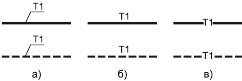
Figure 1
3.9 With simplified graphical representations of the pipeline (in two lines), alphanumeric or numeric designations indicate on the shelves of the leader lines [Fig. 2a)] or directly above the graphic image of the pipeline [Fig. 2b)].
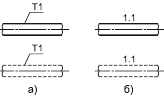
Figure 2
3.10 The number of alphanumeric or numeric signs to be placed on the pipelines should be minimal, but providing an understanding of the drawing.
3.11 Dimensions of pipelines diameters, with their graphic symbols and simplified graphic images, indicate in mm without a unit of measure and are applied on the shelves of the leader lines or directly above the graphic image of the pipeline in the following form:
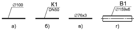
Figure 3