** The designation can be used with any of the additional signs characterizing the position of the regulating body when the power supply is off or the control signal is lost.
This page is not the original of GOST 21.208-2013. Just a short review. Translation may be inaccurate.
4 Symbols of instruments and means of automation in diagrams
4.1 Graphical designations
4.1.1 Graphical symbols of devices, means of automation and communication lines should conform to the Table 1.
| Table 1 | |
| Description | Symbol |
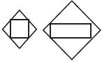
| 1 Located in field: | |
| a) basic designation | |
| b) alternate designation | |
| 2 Device, apparatus mounted on the panel: | |
| a) basic designation | |
| b) alternate designation | |
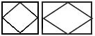
| 3 Functional blocks of digital equipment (controller, system unit, a monitor interface unit, etc.). | |
| 3 The device, installed outside the panel | |
| a) basic designation | |
| b) alternate designation | |
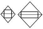
| 4 Device installed on the panel* | |
| a) basic designation | |
| b) alternate designation | |
| 5 Generic actuator. Basic designation | |
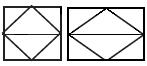
| 6 The actuator, when de-energized or control signal is lost: | |
| a) to open position | |
| b) to closed position | |
| c) locked in last position | |
| 7 The actuator with an additional manual drive** | |
| * When placing automation equipment in cabinets, racks designed to accommodate only automation systems, it is allowed not to designate the equipment in rhombs on the diagrams. ** The designation can be used with any of the additional signs characterizing the position of the regulating body when the power supply is off or the control signal is lost. | |
4.2 Letter designations
4.2.1 The basic letter designation of the measured values and functional characteristics of the instruments should correspond to those given in Table 2.
| Let | Measured value | Functional feature of the instrument | |||
| The main indication of the measured value | Additional designation, specifying the measured value | Disp | Output signal gener | Addi | |
| A | Analysis The value charact compo | - | Alarm system | - | - |
| B | Flame, burning | - | - | - | - |
| C | + | - | - | Automatic control | - |
| D | + | Difference | - | - | The magnitude of the deviation from a given measurand (5.11.8) |
| E | Voltage | - | - | Sensing element (5.11.3) | - |
| F | Flow rate | Ratio, fraction | - | - | - |
| G | + | - | Primary indicating device | - | - |
| H | Hand | - | - | - | The upper limit of the measured value (5.11.7) |
| I | Current | - | Secondary indicating device | - | - |
| J | Power | Automatic switching, | - | - | - |
| K | Time, time program | - | - | Control station (5.11.2) | - |
| L | Level | - | - | - | The lower limit of the measured quantity (5.11.7) |
| M | + | - | - | - | The value or the average position (between the upper H and the lower L) |
| N | + | - | - | - | - |
| O | + | - | - | - | - |
| P | Pressure, vacuum | - | - | - | - |
| Q | Quantity | Integration, summation over time | - | + | - |
| R | Radio | - | Record | - | - |
| S | Speed, frequency | Safety device (5.8) | - | Turn on and off, switching, locking (5.11.4) | - |
| T | Temper | - | - | Transfor | - |
| U | Several dissimilar measured values | - | - | - | - |
| V | Vibration | - | + | - | - |
| W | Weight, power | - | - | - | - |
| X | Unsup | - | Auxiliary computer devices | - | - |
| Y | Event, state (5.7) | - | - | Auxiliary computing device (5.11.6) | - |
| Z | Size, position, displ | System of instru | - | + | - |
| Notes. 1 The letters marked with a "+" sign are assigned at the user's choice, and the "-" signs are not used. 2 The numbers of the explanatory items are given in parentheses. | |||||
4.2.2 Additional symbols used to indicate additional functional characteristics of instruments, signal converters and computing devices are given in Table A.1 (Appendix A), the designation of binary logic functions and the symbols of binary logic devices in the schemes are given in Table A.2 (Appendix A ).
5.11 Functional features of devices
5.11.1 The letter A is used to indicate the "alarm" function, regardless of whether the signaling equipment is placed on a shield or for the use of lamps built into the device itself.
5.11.2 The letter K is used to designate a control station having a switch for selecting a control type and a device for remote control.
5.11.3 The letter E is used to designate a sensing element that performs the function of a primary conversion: thermoelectric converters, thermal resistance converters, pyrometer sensors, primary devices of flowmeters, etc.
5.11.4 The letter S is used to designate the contact of the device used only for switching on, off, switching, blocking.
When using the contact of the device, for switching on, switching off and simultaneously for signaling in the device designation use both letters: S and A.
5.11.5 The letter T is used to designate a primary device of a non-indicating instrument with remote signal transmission: manometers, differential pressure gauges, manometric thermometers.
5.11.6 The letter Y is used to refer to an auxiliary device serving as a computing device.
5.11.7 The limits of the measured values, for which, for example, switching on, switching off, blocking, signaling, are allowed, can be specified by adding the letters H and L. The combination of the letters HH and LL is used to indicate two values. The letters are placed to the right of the graphic designation.
5.11.8 The deviation of the function D when combined with the function A (alarm) indicates that the measured variable has deviated from the job or another control point more than by a predetermined number.
5.12 When constructing the letters, not all the functional characteristics of the device are indicated, but only those that are used in this scheme.
5.13 If it is necessary to specify the measured value to the right of the device symbol, it is possible to indicate the name, symbol of this value or its value, for the measured value A indicate the type of analyzer, the designation of the analyzed quantity and the interval of values of the measured parameter.
5.14 For the designation of values not provided for in this standard, it is allowed to use reserve letters. The use of redundant letters must be decoded in the diagram.
5.15 The lines to the device depicted in any point of the graphic symbol (top, bottom, side). If necessary, indicate the direction of signal transmission on the communication lines by arrows.
5.16 Examples of building symbols for instruments and means of automation are given in Table B.1 (Appendix B).
6 Dimensions of symbols
6.1 The sizes of the graphic designations of devices and means of automation in the schemes are given in Table 3.
6.2 Graphic symbols on the diagrams are made by a solid thick main line, and the horizontal dividing line within the graphic designation and communication line is a solid thin line in accordance with GOST 2.303.
| Table 3 | |
| Description | Designation |
| 1 Instrument: | |
| a) basic designation | |
| b) permissible designation | 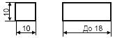 |
| 2 Functional blocks of digital equipment (controller, system unit, interface unit, etc.). | |
| 3 Device (included in the automation circuit) | |
| a) basic designation | 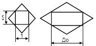 |
| b) permissible designation | 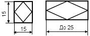 |
| 4 Actuating mechanism | |
Examples of constructing the symbols of instruments and means of automation
| Table B.1 | |
| Description | Designation |
| Primary measuring transducer (sensing element) for measuring temperature, field mounted. For example: a thermoelectric (thermocouple) converter, a resistance thermometer, a thermo-balloon of a manometric thermometer, a pyrometer sensor, etc. | |
| The indicating device for measuring the temperature, field mounted. For example: a mercury thermometer, a manometric thermometer, etc. | |
| The indicating device for measuring the temperature, mounted on the panel. For example: millivoltmeter, logometer, potentiometer, automatic bridge, etc. | |
| A non-indicating device for measuring the temperature with a remote indication, field mounted. For example: a non-indicating thermometric gauge (or any other non-indicating temperature sensor) with pneumatic or electrical transmission | |
| The recording, single-point device for measuring temperature, mounted on the panel. For example: a recording millivoltmeter, a logometer, a potentiometer, an automatic bridge, etc. | |
| The recording device for measuring temperature with an automatic scoring device, mounted on the panel. For example: a multi-point recording potentiometer, an automatic bridge, etc. | |
| The recording, controlling device for measuring the temperature, mounted on the panel. For example: any recording temperature controller (thermometer manometric, millivoltmeter, logometer, potentiometer, bridge automatic, etc.) | |
| The non-indicating temperature regulator, field mounted. For example: dilatometric temperature controller | |
| A registering and controlling set for measuring temperature, equipped with a control station installed on the switchboard. For example: the secondary device and the control unit of "Start" system | |
| A non-indicating device for measuring the temperature with a contact output, field mounted. For example: a temperature relay | |
| The primary device for monitoring the temperature in the automation system |  |
| Temperature measurement. An analog-to-digital converter mounted on a switchboard, included in the automation circuit. |  |
| Bypass panel remote control installed on the switchboard | |
| Switch for electrical measuring circuits (control), switch for gas (air) lines installed on the switchboard | |
| The indicating device for measuring pressure (vacuum), field mounted. For example: any indicating manometer, a differential pressure gauge, a pull gauge, a pressure gauge, a vacuum gauge, etc. | |
| The indicating device for measuring the differential pressure, field mounted. For example: an indicating difmanometer | |
| The non-indicating device for measurement of pressure (vacuum) with remote indication, field mounted. For example: a non-indicating pressure gauge (differential pressure gauge) with pneumatic or electrical data transmission | |
| The recording device for measuring the pressure (vacuum), mounted on the panel. For example: a recording manometer or any secondary device for recording pressure | |
| The device for measuring pressure with a contact output, field mounted. For example: a pressure switch | |
| The indicating device for measuring the pressure (vacuum) with the contact output, field mounted For example: an electrocontact manometer, a vacuum gauge, etc. | |
| Primary measuring transducer (sensing element) for flow measurement, field mounted. For example: an induction flowmeter sensor, etc. | |
| A non-indicating device for measuring the flow rate with a remote indication, field mounted. For example: a non-indicating rotameter with pneumatic or electrical data transmission | |
| A recording device for measuring flow ratio, installed on the panel. For example: any secondary device for registration flow ratio | |
| The indicating device for measuring the flow rate, field mounted. For example: an indicating difmanometer (rotameter) | |
| The integrating device for flow measurement, field mounted. For example: any non-indicating counter-flowmeter with an integrator | |
| The indicating device for measuring the flow, integrating, field mounted. For example: an indicating difmanometer with an integrator | |
| The multiparameter mass flowmeter providing flow and temperature measurement with analog current output 4-20 mA | |
| The device for measuring the flow integrating, with an output for issuing a signal after passing a predetermined amount of substance, field mounted. For example: a counter dispenser | |
| A transducer (sensor) for measuring the level, field mounted. For example: an electric sensor or a capacitive level gauge | |
| The device for measuring the level, indicating, field mounted. For example: a manometer (a differential pressure gauge) used to measure the level | |
| Device for level measurement with remote display unit. Show as two separate blocks with a connecting line in accordance with GOST 21.408 | |
| The device for level measurement with a contact output, field mounted. For example: a level switch used for blocking and signaling the upper level | |
| A non-indicating device for measuring the level, with a remote transmission of data, field mounted. For example: a non-indicating level sensor with pneumatic or electrical data transmission | |
| The non-indicating device for measuring the level, controlling, with a contact output, field mounted. For example: an electric level regulator. The letter H in this example means a lock on the upper level | |
| An indicating device for level measurement, with a contact output, mounted on the switchboard. For example: a secondary indicating device with an alarm signal. The letters H and L indicate the signaling of the upper and lower levels | |
| The non-indicating device for measuring the density of the solution, with a remote indication, field mounted. For example: the sensor of a densimeter with pneumatic or electrical remote indication | |
| The indicating device for measuring the dimensions, field mounted. For example: a device for measuring the thickness of steel tape | |
| The indicating device for measuring the electrical value, field mounted. For example: | |
| - voltage; | |
| - current; | |
| - power | |
| The device for controlling the process according to the time program, installed on the panel. For example: command electro-pneumatic device (CEP), multi-circuit time relay | |
| The registering device for measuring humidity, installed on the panel. For example: a secondary moisture meter | |
| Primary transducer (sensor) for measuring product quality, field mounted. For example: a pH meter | |
| The indicating device for measuring the quality of the product, field mounted. For example: a gas analyzer for monitoring oxygen in flue gases | |
| The registering and controlling device for measuring product quality, installed on a panel. For example: the secondary recording regulator of the concentration of sulfuric acid in solution | |
| An indicating device for measuring radioactivity, with a contact output, field mounted. For example: a device for indicating and signaling the maximum permissible concentrations of α and β rays | |
| The registering device for measuring the speed of rotation of the drive, mounted on the switchboard. For example: a secondary tachometer device | |
| The registering device for measuring several dissimilar values, field mounted. For example: a differential pressure meter with an additional pressure record. The inscription decoding the measured values is applied to the right of the instrument | |
| The indicating device for measuring the viscosity of the solution, field mounted. For example: an indicating viscometer | |
| The indicating device for measuring the mass of the product, with a contact output, field mounted. For example: an electronic-tensometric signaling device | |
| The non-indicating device for control of flame extinction in the furnace, with a contact output mounted on the panel. For example: a secondary safety device | |
| Signal converter mounted on the switchboard. The input signal is electric, the output signal is also electrical. For example: a measuring transducer for converting an emf from a thermoelectric thermometer into a direct current signal | |
| Signal converter, field mounted. Input signal is pneumatic, output is electric | |
| A computing device that performs the function of multiplication. For example: the factor for a constant coefficient K, installed on the panel | |
| Starting equipment for controlling the electric motor (switching on, switching off the pump, opening, closing the valve, etc.). For example: magnetic starter, contactor, etc. The use of the reserve letter N should be specified on the scheme | |
| The equipment for manual remote control (switching on, switching off the engine, opening, closing the closing body, changing settings of the controller) installed on the switchboard. For example: button, control key | |
| The equipment for manual remote control, equipped with a device for signaling, installed on the switchboard. For example: button with built-in light, control key with illumination, etc. | |
| The device for level measurement with a contact output, field mounted. For example: a level switch used to signal the upper level and the lower level with a signal output at four level values |  |
| Regulating valve, closing when power is cut off with manual control function | |
| Note. In the designation of the device or apparatus, for all examples, a square or a rectangle may be used instead of a circle. | |