Note. The designation can be used with any of the additional signs characterizing the position of the regulating body when the power supply or the control signal is interrupted

This page is not the original of GOST 21.404-85. Translation may be inaccurate.
1.1.1. Graphical symbols of devices, means of automation and communication lines should conform to the Table 1.
Table 1
| Description | Symbol |
| 1. Located in field: | |
| a) basic designation | |
| b) alternate designation | |
| 2. Located on central or main panel or console: | |
| a) basic designation | |
| b) alternate designation | |
| 3. Generic actuator. Basic designation | |
| 4. The actuator, when de-energized or control signal is lost: | |
| a) to open position | |
| b) to closed position | |
| c) locked in last position | |
| 5. The actuator with an additional manual drive Note. The designation can be used with any of the additional signs characterizing the position of the regulating body when the power supply or the control signal is interrupted | |
| 6. Communication line. General designation | |
| 7. Crossing communication lines without connecting to each other | |
| 8. Crossing of lines with connection to each other | |
1.1.2. Generic permanent instrument connection to process line is represented by a continuous thin line connecting the process pipeline or apparatus with the instrument (Fig. 1). If it is necessary to specify the specific location of the sampling device (inside the contour of the technological apparatus), it is indicated by a circle with a diameter of 2 mm (Fig. 2).
 Fig. 1 | 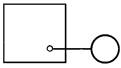 Fig. 2 |
1.2.1. The basic letter designation of the measured values and functional characteristics of the instruments should correspond to those given in Table 2.
Table 2
| Measured value | Functional feature of the instrument | ||||
| Letter | The main indication of the measured value | Additional designation, specifying the measured value | Disp | Output signal gener | Addi |
| А | + | - | Alarm | - | - |
| В | + | - | - | - | - |
| С | + | Control | |||
| D | Density | Difference | - | - | - |
| E | Voltage | - | + | - | - |
| F | Flow Rate | Ratio, fraction | - | - | - |
| G | Size, position | + | |||
| H | Hand | The upper limit of the measured value | |||
| I | + | - | Indicate | - | - |
| J | + | Automatic switching | |||
| К | Time, Time Schedule | - | - | + | - |
| L | Level | The lower limit of the measured value | |||
| M | Humidity | - | - | - | - |
| N | + | - | - | - | - |
| O | + | - | - | - | - |
| P | Pressure, Vacuum | - | - | - | - |
| Q | Quantity | Integrate, Totalize | + | ||
| R | Radiation | - | Record | - | - |
| S | Speed, Frequency | Switch | |||
| T | Tempe | - | - | + | - |
| U | Multiva | ||||
| V | Viscosity | - | + | - | - |
| W | Weight | - | - | - | - |
| X | Unclassified | - | - | - | - |
| Y | + | - | - | + | - |
| Z | + | - | - | + | - |
Note. The letters marked with an «+», sign are reserved, the «-» sign is not used.
1.3.1. Dimensions of graphic designations of instruments and automation means in the diagrams are shown in Table 3.
Table 3
| Description | Symbol |
| Instrument: | |
| a) basic designation | |
| b) alternative designation |  |
| Actuating mechanism |  |
Additional letter symbols used to indicate additional functional features of devices, signal converters and computing devices
1. Additional letters indicating the functional characteristics of the instrument are given in the Table 1
Table 1
| Name | Symbol | Description |
| Sensor | E | The device performs a primary conversion: thermoelectric transducers, resistance thermometers, gauges, pyrometers, orifice device flowmeters, etc. |
| Remote transmission | T | Non-indicating devices with remote signal transmission: manometers, differential pressure gauges, manometric thermometers |
| Control station | K | Devices having a switch to select the type of control and a device for remote control |
| Conversion, computational functions | Y | For the designations of signal converters and computing devices |
2. Additional letter designations of signal converters, computing devices, are given in Table 2
Table 2
| Description | Symbol |
| 1. The kind of energy signal: | |
| - electric | Е |
| - pneumatic | P |
| - hydraulic | G |
| 2. Types of signal: | |
| - analogue | A |
| - discrete | D |
| 3. The operations performed by the computing device: | |
| - summation | ∑ |
| - multiplying the signal by a constant coefficient k | k |
| - multiplying two or more signals one upon another | x |
| - signal division | : |
| - raising the value of the signal f to the power of n | ƒn |
| - extraction from the signal value of the root of degree n | √n |
| - logarithm | lg |
| - differentiation | dx/dt |
| - integration | ∫ |
| - signal sign change | х(-1) |
| - upper signal limit | max |
| - lower signal limit | min |
| 4. Communication with the data center: | |
| - signal transmition | Bi |
| - signal reception | Bo |
3. The order of construction of designations with the use of additional letters is taken as follows:
- the main designation of the measured quantity;
- one of the additional letters E, T, K or Y.
4. When constructing the symbols for signal converters and computing devices, the inscriptions that determine the type of transformation or operations performed by the computing device are applied to the right of the device's graphic designation.
ANNEX 2
Examples of constructing designation for instruments and means of automation
| Num. | Designation | Description |
| 1 | Primary measuring transducer (sensing element) for measuring temperature, field mounted. An example: a thermocouple, a resistance thermometer, a thermo-balloon of a manometric thermometer, a pyrometer sensor, etc. | |
| 2 | Device for measuring the temperature displaying, field mounted. An example: a mercury thermometer, a manometric thermometer, etc. | |
| 3 | The device for measuring the temperature displaying, mounted on the panel. An example: millivoltmeter, logometer, potentiometer, automatic bridge, etc. | |
| 4 | The non-indicating device for measuring the temperature with a remote indication, field mounted. An example: a non-indicating thermometer gauge (or any other temperature sensor) with a pneumatic or electronic data transfer | |
| 5 | The device for measuring the temperature of a single point, recording, mounted on the panel. An example: a recording millivoltmeter, a logometer, a potentiometer, an automatic bridge, etc. | |
| 6 | The device for measuring temperature, recording, installed on the panel. An example: a multi-point recording potentiometer, an automatic bridge, etc. | |
| 7 | The recording device for measuring the temperature, controlling, installed on the panel. An example: any recording temperature controller (thermometer manometric, millivoltmeter, logometer, potentiometer, bridge automatic, etc.) | |
| 8 | The non-indicating temperature regulator, field mounted. An example: dilatometric temperature controller | |
| 9 | A set for measuring temperature, controlling, equipped with a control station installed on the panel. An example: a secondary device and a controlling unit of the "Start" system | |
| 10 | A non-indicating device for measuring the temperature with a contact output, field mounted. An example: a temperature relay | |
| 11 | Bypass panel for remote control installed on the switchboard. | |
| 12 | Switch for electrical measuring circuits (control), switch for gas (air) lines installed on the switchboard. | |
| 13 | The device for measuring the pressure (vacuum) displaying, field mounted. An example: any displaying manometer, a differential pressure gauge, a pull gauge, a pressure gauge, a vacuum gauge, etc. | |
| 14 | The device for measuring the differential pressure, indicating, field mounted. An example: an indicating difmanometer. | |
| 15 | A non-indicating for measurement pressure (vacuum) with remote indication, field mounted. An example: a non-indicating pressure gauge (differential pressure gauge) with pneumatic or electric power transmission. | |
| 16 | The recording device for measuring pressure (vacuum), mounted on the panel. An example: a recording manometer or any secondary device for recording pressure. | |
| 17 | The device for measuring pressure with a contact output, field mounted. An example: a pressure switch. | |
| 18 | An indicating device for measuring the pressure (vacuum) with a contact outputs, field mounted. An example: an electrocontact manometer, a vacuum gauge, etc. | |
| 19 | 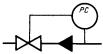 | A pressure regulator that operates without using an external power source (direct pressure regulator). |
| 20 | Primary measuring transducer (sensing element) for flow measurement, field mounted. An example: an orifice plate, a nozzle, a Venturi pipe, an induction flow meter sensor, etc. | |
| 21 | A non-indicating device for measuring the flow rate with a remote indication, installed in the field. An example: a non-indicating difmanometer (rotameter), with pneumatic or electric data transmission. | |
| 22 | The recording device for measuring the ratio of flow rates, installed on the panel. An example: any secondary device for recording the flow rate ratio. | |
| 23 | The indicating device for measuring the flow rate, field mounted. An example: an indicatring difmanometer (rotameter). | |
| 24 | The integrating device for flow measurement, field mounted. An example: any non-indicating counter-flowmeter with an integrator. | |
| 25 | The indicating and integrating device for measuring the flow rate, field mounted. An example: an indicating difmanometer with an integrator. | |
| 26 | The integrating device for measuring flow rate, with a device for issuing a signal after passing a predetermined amount of substance, field mounted. An example: a counter dispenser. | |
| 27 | A sensor for measuring the level, field mounted. An example: an electric or a capacitive level gauge. | |
| 28 | The indicating device for measuring the level, field mounted. An example: a manometer (a differential pressure gauge) used to measure a level. | |
| 29 | The device for measuring the level with a contact output, field mounted. An example: a level switch used to lock and signal the upper level. | |
| 30 | A device for measuring level, non-indicating, with a remote transmission of data, field mounted. Аn example: a level non-indicating sensor with pneumatic or electric data transmission. | |
| 31 | A non-indicating controlling device for measuring the level, with a contact output, field mounted. A example: an electric level regulator. The letter H in this example means a lock on the upper level. | |
| 32 | A device for level measurement, indicating, with a contact output, mounted on the switchboard. An example: a secondary indicating device with alarm switch. The letters H and L indicate the signaling of the upper and lower levels. | |
| 33 | The non-indicating device for measuring density, with a remote indication, field mounted. An example: a sensor of a density meter with pneumatic or electrical data transmission. | |
| 34 | The indicating device for measuring the dimensions, field mounted. An example: the indicating device for measuring the thickness of steel tape. | |
| 35 | Прибор для измерения любой электрической величины показывающий, установленный по месту. | |
| Example: | ||
| Voltage* | ||
| Current* | ||
| Power* | ||
| 36 | The device for controlling the process according to the temporary program, installed on the switchboard. An example: command electro-pneumatic device (CEP), multi-circuit time relay. | |
| 37 | The recording device for measuring humidity, installed on the panel. An example: a secondary moisture meter | |
| 38 | Primary measuring transducer (sensor) for measuring product quality, field mounted. An example: a pH meter | |
| 39 | The device for measuring the quality of the product showing, field mounted. An example: a indicating gas analyzer for controlling the oxygen content in flue gases. | |
| 40 | The registering and controlling device for measuring product quality, installed on the panel. An example: a secondary recording device for the regulator of the concentration of sulfuric acid in solution. | |
| 41 | An indicating device for measuring radioactivity, with a contact output, field mounted. An example: a device for indicating and signaling of maximum permissible concentrations of a and R-rays. | |
| 42 | The recording device for measuring the speed of rotation of the drive, mounted on the switchboard. An example: a secondary tachogenerator device | |
| 43 | The registering device for measuring several dissimilar values, field mounted. An example: a self-recording differential pressure meter with an additional pressure record. The inscription deciphering the measured values is applied to the right of the instrument. | |
| 44 | The device for measuring the viscosity of the solution, indicating, field mounted. An example: an indicating viscometer. | |
| 45 | The indicating device for measuring the mass of the product, with a contact output, field mounted. An example: the electron-tensometric device with alarm function. | |
| 46 | The non-indicating device for control of flame extinction in the furnace, with a contact output, mounted on the panel. An example: a secondary device of the ignition-protective device. The use of the reserved letter B must be specified on the field of the scheme. | |
| 47 | Signal converter mounted on the switchboard. The input signal is electric, the output signal is also electrical. An example: a measuring transducer serving to convert an emf of thermoelectric thermometer into a DC signal. | |
| 48 | Signal converter, field mounted. The input signal is pneumatic, the output signal is electric. | |
| 49 | A computing device that performs the function of multiplication. For example: multiplier by constant coefficient K. | |
| 50 | Equipment for controlling the electric motor (switching on, switching off the pump, opening, closing the valve, etc.). An example: magnetic starter, contactor, etc. The use of the reserve letter N must be specified on the field of the scheme. | |
| 51 | The equipment intended for manual remote control (switching on, switching off the engine, opening, closing the closing body, changing the task to the controller) installed on the panel. An example: button, control key. | |
| 52 | The equipment intended for manual remote control, equipped with a contacts for signaling, installed on the panel. An example: a button with a built-in light, a control key with a backlight, etc. | |
* The inscriptions describing a particular measured electrical quantity are located either next to the instrument or in the form of a table on the diagram.