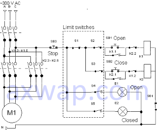
Fig. 1. Control curcuit of the electric valve with four limit switches
Here are presented the simplest control circuits for electric valves, used in instrumentation and automation on the basis of limit switches.
The control circuit of the electric valve in the simplest case is a block of limit switches connected with control buttons and electromagnet relays (starters). In most cases, it contains a manual control interlock.
It can contain a current switch-off relay (instantaneous shutdown when the current setpoint is exceeded) and a telemetry position indicator of the valve. Not considered in this article.
Figures 1 and 2 show two valve control circuits. In the first, four limit switches are used to control the motor and the gate valve signaling lamps, in the second - two.
Common elements are:
K1 - electromagnet relay (starter) for opening;
K2 - electromagnet relay (starter) for closing;
SB1 - the "Open" button;
SB2 - the "Close" button;
SB3 - the "Stop" button;
E1 - the lamp indicating the opening of the valve "Open";
E2 - the lamp indicating the closing of the valve "Closed";
S6 - thermal relay that turns off the electric motor when the load current increases - jamming of the valve, reducer, disappearance of one phase.
S1 - a safety switch of the electrical control circuit. When the valve is switched to manual control, it blocks the control circuits of the electric valve, preventing accidental activation of it from the control panel, so that technological personnel do not suffer, etc.
S2 - S5 - contacts of the end switches, controlled by the cam mechanism of the unit, rigidly mechanically connected to the controllable valve.
K1.3 - K1.5, K2.3 - K2.5 - power contacts of relays K1 and K2, supplying voltage 380 V AC to the motor.
Fig. 1. Control curcuit of the electric valve with four limit switches
Operating principle
When the electric valve is in the middle position and the manual mode is off, the phase "C" passes through the contacts of the stop button SB3, the closed contact of the manual mode switch (S1) and the limit switches S2 and S3 to the contacts of the buttons SB1 and SB2 (open, close).
When the SB1 "Open" button is pressed, the relay K1 activates and is self-triggered via contacts K1.1. Through its power contacts K1.2 to K1.5, voltage is applied to the motor M1, the valve starts to open until the button SB3 "Stop" is pressed or the cam mechanism of the limit switch unit opens contact S2, which is responsible for stopping the valve in the "Open" position. When this position is reached, i.e. the gate in the "Open" position, the contact of the switch S4 must be closed (it is set by the corresponding cam in the limit switch unit), the lamp E1 indicating the open position of the gate starts to light. Further attempts to press the "Open" button do not lead to anything. The contacts of the S2 switch are open and no voltage is applied to the SB1 "Open" button. However, the SB2 "Close" button receives voltage through the contacts S3, when it is pressed, the valve closes.
Similarly, the mechanism for closing the valve is implemented. If it is in the middle or open position, when the manual mode is switched off, the "C" phase passes through the contacts of the stop button SB3, the closed contact of the manual switch (S1) and the closed limit switch S3 to the SB2 "Close" button. When it is pressed, the relay K2 is activated and self-trapped via contacts K2.1, the voltage through its power contacts is fed to the motor M1 (with the phases "B" and "C" reversed) and the valve starts to close until the button SB3 "Stop" is pressed or the limit switch S3 is open when the gate valve closed. The E2 lamp also lights up, indicating that the valve is closed. To do this, the pusher of the cam mechanism must be correctly positioned, which is responsible for closing the contact of the switch S4.
Normally closed contacts of relays K1.2 and K2.2 open in opposite directions when the corresponding relay trips, thereby preventing simultaneous activation of both relays, which would lead to short circuit.
Advantages
The manual mode switch S1 is directly connected to the circuit of the contact block of the S2-S5 limit switches, which makes it possible to mount the control circuit of the gate valve from the control panel with a 5-wire cable.
Disadvantages
In this circuit for controlling the electric valve, four limit switches are used, two for switching off the control circuits, two for switching on the indicator lamps, which requires the settings of each limit switch separately. But if by technology it is required that the indication lamps of the end position light up earlier than this position is reached, then this can be a worthiness.
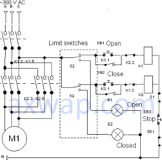
Fig. 2. Control circuit of electric valve with two limit switches
Operating principle
It is similar to the previous circuit, except that manual switch contact S1 are out of the limit switch block, i.e. phase "C" is fed directly to contacts S2 and S3. This allows to use two limit switches only, using their normally open contacts to turn on the indicating lamps of the valve position. This is very convenient, since the indicating lamps only light up at the moment when this or that limit switch actually worked.
Advantages
As already mentioned above, the indicating lamps of the valve lights only at the moment when this or that limit switch actually worked.
Disadvantages
If you want to connect the manual mode switch S1, then when installing the limit switch unit on the gate valve, two additional wires are required in the cable. That is, there should be at least seven wires in the cable.